6WIND sets the standard for 5G virtual security gateways
6WIND has completed three demos of its virtual security gateway (vSecGW), in close collaboration with two of the largest global Tier-1 mobile network operators (MNOs) in Europe. The results were outstanding, demonstrating – among other things – that 200 Gbps of aggregate IPsec throughput with IMIX traffic can readily be achieved on a stock COTS[1] server, while utilizing just 15 CPU cores and requiring zero hardware acceleration.
In fact, the used reference server and the vSecGW software could handle a much higher IPsec throughput, up to an impressive 480 Gbps with IMIX[2], if all cores were allocated to the vSecGW and if sufficient network interfaces were present to allow enough traffic into the server. The 200 Gbps ceiling in our demos is set by the port count (2) and port capacity or line-rate limitations (200 Gbps aggregate or 100 Gbps full-duplex) of the selected reference NIC card.
The obtained results prove that virtualization and disaggregation of the 4G or 5G security gateway is perfectly feasible, and opens the door to a fully virtualized or even cloud-native security gateway to be deployed in private or public clouds. Virtualization should lower the Total Cost of Ownership (TCO), reduce or eliminate vendor lock-in, while accelerating the pace of network innovation.
First Demo Setup
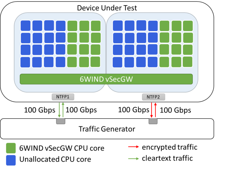
The first demo setup is designed to prove that the 6WIND vSecGW can readily deliver 200 Gbps of IPsec throughput on a standard COTS server, with a modest number of CPU cores. Refer to Figure 1.
Figure 1: COTS server delivers 200 Gbps of aggregate IPsec throughput with – in this example – 24 CPU cores allocated to our vSecGW.
The device under test (DUT) configuration in Figure 1 consists of the following hardware elements:
- Intel-based COTS server with Dual Intel Xeon Gold 6348 @ 2.6 GHz (2 x 28 cores) CPUs,
- Intel E810-CQDA2 (Gen4) NIC card with 2 x 100/50/25/10 GbE ports.
The configuration of the DUT is as follows:
- Hyperthreading is disabled,
- vSecGW (VSR 3.4) installed bare-metal as a Physical Network Function (PNF),
- 32 IPsec tunnels established to emulate multiple eNodeB/gNodeB devices,
- The AES-256-GCM algorithm is used,
- 8, 24 or 32 CPU cores are respectively allocated to the vSecGW, to measure the attainable IPsec throughput with different numbers of CPU cores.
Bidirectional traffic is generated by a traffic generator and runs between the two interfaces of the Security Gateway; NTFP1 (cleartext) and NTFP2 (encrypted) interfaces on the NIC card (Figure 1). Two traffic profiles were used for establishing the benchmark results:
- IMIX: 64B (58%), 590B (33.3%), 1514B (8.3%) (average: ~350B)
- IMIX2: 64B (8%), 127B (36%), 255B (11%), 511B (4%), 1024B (2%), 1539 (39%) (average ~700B).
Note: IMIX2 is a customer-specific typical 5G traffic profile.
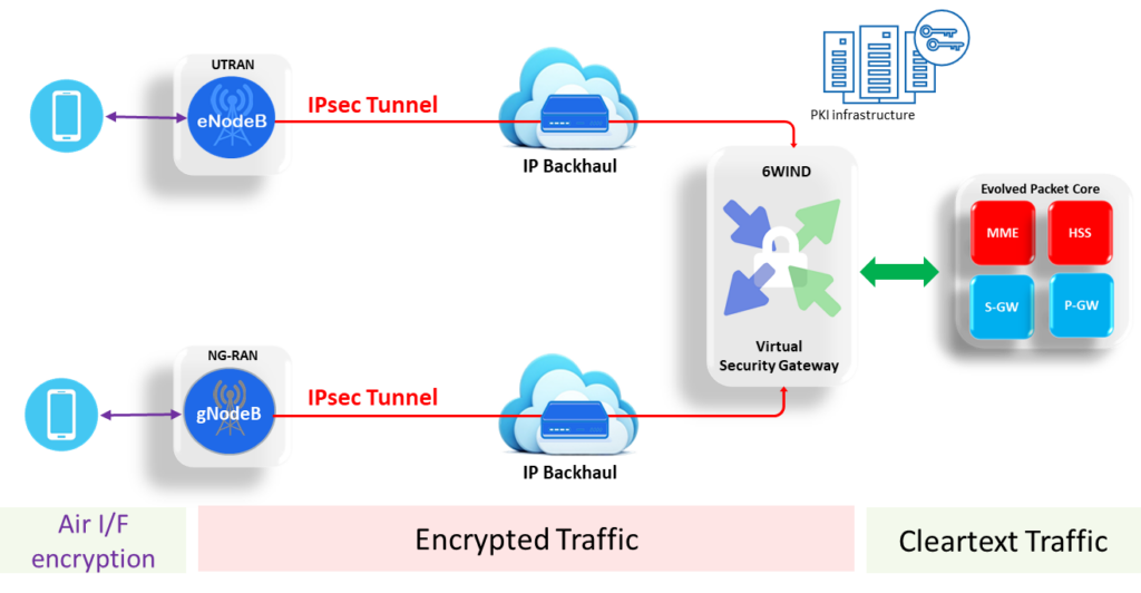
The configuration that we’re modeling is the one depicted in Figure 2. This configuration shows, in a simplified way, a typical IPsec and virtual security gateway deployment in a 4G / 5G radio access network (RAN). In such a RAN network, the air interface between the User Equipment (UE) and the eNodeB (4G) or gNodeB (5G) – in the sequel collectively referred to as NodeB – is by default secured by encryption. Yet those individual UE encryption tunnels are terminated at the NodeB. The Node B can then set up one or more IPsec tunnels to the edge core network (EPC/5GC). There the Virtual Security Gateway is situated, terminating those IPsec tunnels, and sending cleartext to the EPC/5GC.
Figure 2: typical IPsec and Virtual Security Gateway deployment in a 4G / 5G mobile network.
The IPsec tunnels between the NodeB and Core network are required for two reasons:
- To warrant the RAN network integrity. Some NodeBs, especially micro- and (often indoor) picocell NodeBs will be deployed by 3rd party contractors or even consumers in spaces with no physical security perimeter whatsoever. Much of the traffic emanating from those NodeBs will subsequently be hauled over 3rd party or public transport infrastructure. It’s therefore of paramount importance that all of the MNO’s NodeBs are authenticated (tamper-proofing) and that only authenticated RAN network elements can connect to the EPC or 5GC, because the entire network could otherwise be compromised. In other words: unauthorized NodeBs would provide a good attack vector.
- To securely encrypt all payload from the UE all the way to the EPC/5GC. This encryption between the NodeB and the EPC/5GC is required to protect the data integrity and privacy for the User Plane, Control Plane and Management Plane. It precludes eavesdropping or manipulation of the data through, for example, a “man in the middle” attack.
In our demo, we achieve an aggregate IPsec throughput of up to 200 Gbps – depending on the number of used CPU cores and the used traffic profile. The 200 Gbps performance ceiling is dictated by the maximum line rate of our setup, which has two network interfaces supporting up to 100 Gbps full-duplex (200 Gbps aggregate) of throughput.
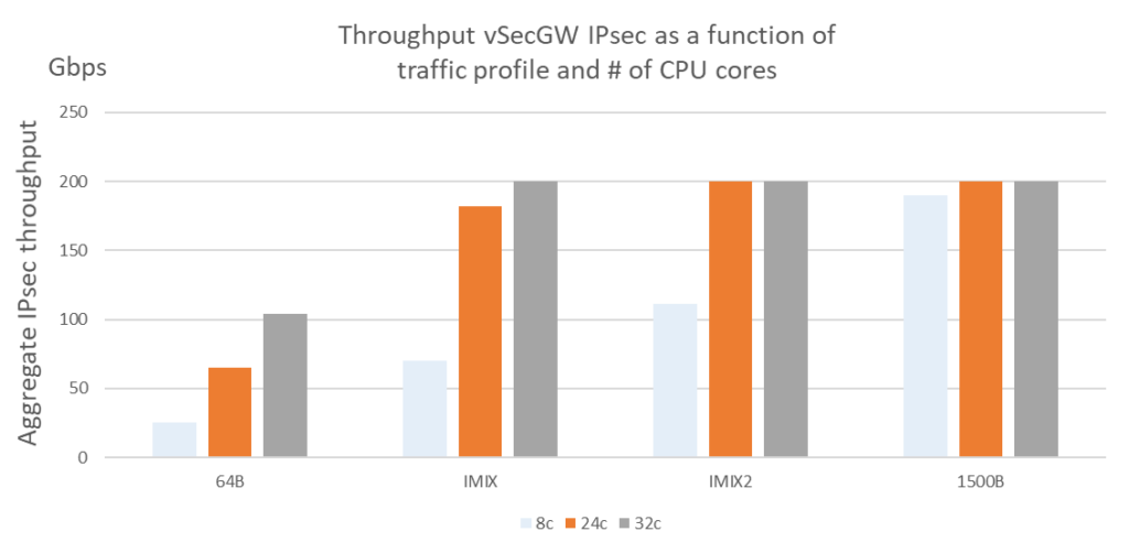
Figure 3: Throughput vSecGW IPsec as a function of traffic profile and the number of engaged CPU cores.
As can clearly be seen in Figure 3, the IPsec throughput strongly depends on the (average) packet size, or the packet size (frame length) distribution. If all packets would be just 64 Bytes long, then even 32 CPU cores would deliver an IPsec throughput just north of 100 Gbps. At the other end of the spectrum, if all packets were 1500 Bytes (or larger), then a mere 8 cores (four times less cores) would suffice to cater for around 190 Gbps (almost 90% more) of IPsec throughput.
In carrier network, packets come in different sizes. In order to ascertain how our vSecGW performs in a realistic environment, the traffic generator loaded it with twi packet profiles: IMIX (Generic Internet Profile) and IMIX2 (5G traffic profile supplied by a Tier-1 MNO).
With IMIX, we hit ~180 Gbps with 24 cores (~7,5 Gbps per core). As IPsec throughput of the 6WIND vSecGW scales linearly with the number of CPU cores allocated to it, we would attain 200 Gbps with almost 27 (26,7) cores.
With IMIX2, we achieved ~110 Gbps with just 8 CPU cores (~13,75 Gbps per core). This extrapolates to 15 (14,5) cores to hit the 200 Gbps line rate. Hence, we can confidently state that our selected 56-core server set-up can deliver 200 Gbps of IPsec throughput under all realistic circumstances and that under representative circumstances, 15-24 cores will suffice to hit or exceed this performance target.
Second Demo Setup
Where the first demo setup focuses on demonstrating sheer performance and resource efficiency in terms of Gbps of IPsec throughput per CPU core, the second setup focuses on demonstrating carrier-grade availability and redundancy.
Running 200+ Gbps of aggregate traffic through one single network element represents a massive single point of failure risk for all sub-tended network elements, like for example NodeBs. Partial or complete failure of a single security gateway can isolate or compromise the service to dozens or even hundreds of NodeBs, or CPEs, serving a large geographical area with tens or hundreds of thousands of subscribers.
It’s therefore of paramount importance that all those network elements that serve a large geographical area or a large number of customers are implemented in a redundant fashion.
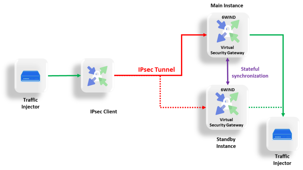
Figure 4: Demonstrating the carrier-grade redundancy of or vSecGW solution.
In this specific demo – refer to Figure 4 – we have two virtual security gateways deployed as Virtual Network Functions (VNFs). High availability is ensured by a stateful synchronization of IPsec tunnels (Security associations and sequence numbers) between the Main and the Standby instances. This configuration can also be described in telecommunications lingo as an N+1 hot-standby configuration, with N=1.
The stateful synchronization or hot standby setup ensures a fast (within 300 ms) and revertive switchover between the two instances, with close to no significant traffic interruption, and thereby – provided that it’s implemented on mutually independent hardware instances – it caters for extremely high availability.
Although the failover will not be hitless – some traffic will be lost and will have to be retransmitted – the service disruption will not be noticeable from a customer or service perspective, and the highest Quality of Experience (QoE) will be assured.
Figure 5: the impact of N+1 (N=1) redundancy on network element downtime.
Figure 5 gives us a rough indication by how much N+1 redundancy (with N=1) can pare down network element unavailability or downtime, and what the “extremely high availability” that we minted above entails. One important underlying assumption in this figure is that the two (virtual) network elements shall not share any single point of failure, like a common hardware (server, NIC), power supply, UPS[3] or battery backup unit system etc. Ideally, those mutually redundant network elements are located at different sites (= geographical redundancy), but that isn’t mandatory.
If we assume that each of the network elements can achieve a 99.995% annual availability (hardware and software) independently, which is a high availability, but not unrealistic for climate-controlled equipment, we’ll experience 26 minutes of annual downtime – on average – for an unprotected system, assuming that it will self-heal. It is beyond the scope of this article to dwell on the mean time to repair (MTTR) and other factors that need to be taken into account to calculate the true (un)availability figure for an unprotected network element that will not self-heal. It is evident that most HW failures, unlike certain SW failures, do not fall in the self-healing category.
While 26 minutes of annual downtime might be acceptable at the access (far edge) side of the network, serving a limited number of customers, it is definitely not acceptable at the edge of or inside the 4G/5G core network, where traffic from a large geographical area and from many customers is aggregated into a comparatively small number of high-capacity network elements. Hence, it’s wise to deploy a redundant vSecGW, as previously outlined in Figure 4. By doing so, the annual unavailability – the likelihood of both the main and standby systems being unavailable simultaneously – drops from 26 minutes to a mere 0.079 seconds per annum. That represents an improvement factor of 20,000, a whopping four orders of magnitude. This number only applies to an instantaneous or hitless redundancy failover. In case the failover imparts a delay, then annual loss of service will be of longer duration than calculated above.
Third Demo Setup
This demo setup resembles the first demo setup, with some notable differences to make it more realistic in a 5G RAN setting – refer to Figure 6.
Figure 6: Test setup with asymmetric traffic loading, a gNodeB simulator and 1000 instead of 32 IPsec tunnels. The traffic on the left and right hand side is clear and the traffic in the middle is encrypted.
The traffic generator on the left-hand side simulates UE traffic, and that traffic is fed to a gNodeB simulator to more closely mimic real-life 5G RAN network traffic. Moreover, the traffic load is asymmetric (90% downlink, 10% uplink), which is more representative of RAN traffic than symmetric traffic, as is the presence of a substantial number of – in this case 1000 – IPsec tunnels.
The packet size distribution used by the traffic generator in this demo setup is the standard IMIX distribution. As we’ve seen in Demo 1, that distribution is less favourable in terms of vSecGW throughput than the more appropriate (for a 5G RAN) “5G style” IMIX2 distribution.
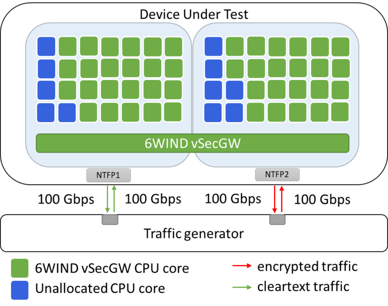
In this demo setup, we allocated 45 CPU cores to the vSecGW, as depicted in Figure 7, although this allocation was not dictated by the workload. In other words: a smaller CPU allocation would have sufficed.
Figure 7: 45 CPU cores are allocated to demo scenario 3.
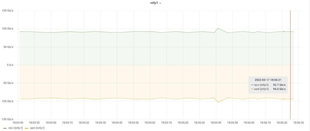
The IPsec throughput performance of the system presented in Figure 6 is illustrated in the figures below.
Figure 8: traffic sent and received through interface NTFP1.
We can tell from Figure 7 that the average aggregate throughput on interface NTFP1 of the DUT is approximately 187 Gbps. A similar picture emerges if we look at interface NTFP2 (not shown).
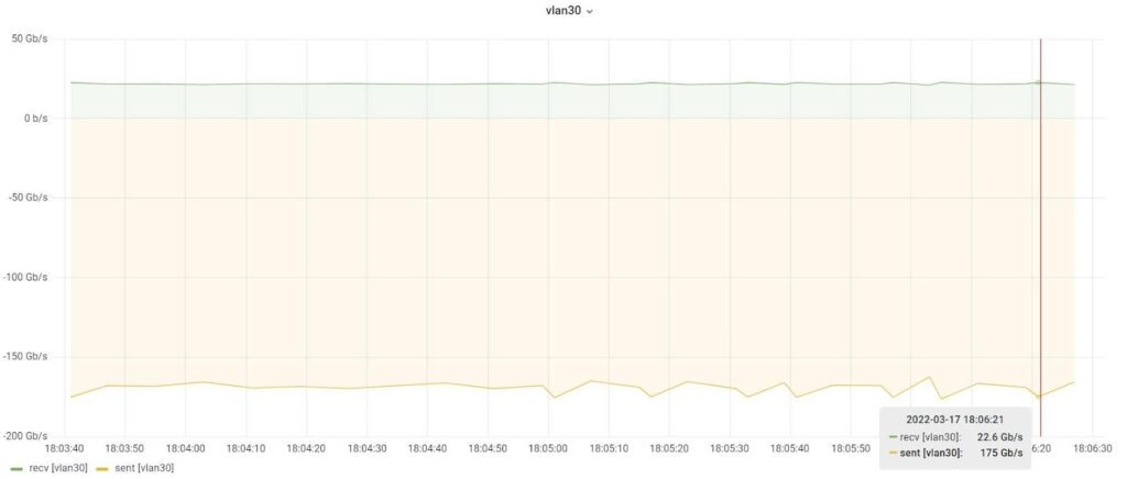
Figure 9: encrypted traffic throughput between the vSecGW and the gNodeB simulator in Figure 6.
Figure 8 shows the volume of encrypted IPsec traffic flowing between the vSecGW and the gNodeB simulator in Figure 6. In this figure, the green plot represents the 10% uplink traffic, in the order of 22,6 Gbps, and the beige plot represents the 90% downlink traffic, in the order of 175 Gbps. The aggregate IPsec traffic that is handled by our server averages close to 198 Gbps.
Conclusion
Our Tier-1 MNO demos have proven that the 6WIND vSecGW virtual security gateway can comfortably support 200 Gbps of aggregate IPsec traffic on a plain, general-purpose COTS server, without leaning on any accelerators or special-purpose hardware.
Depending on the type, number and type of CPU cores, the number and type of network interfaces, and the traffic packet size distribution, the 6WIND vSecGW has the potential to digest an impressive 770 Gbps of IPsec payload on a single server instance.
We have furthermore proven that vSecGW can be implemented as an N+1 redundant (virtual) network element, providing for carrier-grade availability and a fast failover, which is a must-have for deployment in any public, large-scale mobile network.
The most important conclusion is that we can now confidently disaggregate and virtualize the security gateway in a carrier setting, including the security gateway that serves large-scale mobile 4G and 5G networks. Virtualization is a means to an end: accelerating network innovation while at the same time paring down Total Cost of Ownership (TCO). And this is exactly what 6WIND do.
Contact us for more information or to schedule a free trial of our VSR solutions.
[1] Commercial Off-The-Shelf.
[2] Internet MIX: refers to typical Internet traffic.
[3] Uninterruptible Power Supply.

