As the Internet has grown, the need for securing communications between hosts has become mandatory. Whether in transport mode or in tunneling mode, IPsec among other solutions became, nowadays, a widely used solution to secure communications between hosts.
The most common issue that is encountered when connecting two sites together using a Virtual Private Network (VPN) is trying to build a VPN with overlapping networks where both sites happen to use the same Private IP addresses. Connecting two networks with overlapping subnets, if not configured the right way, can lead to IP conflicts and traffic errors.
This blog will help you learn how to correctly address this problem and build a functional site-to-site VPN connection. The configuration we will provide in this blog enables the 6WIND Virtual Security Gateway vRouter to direct traffic to the correct address on the correct network.
A: Dealing With Overlapping Networks
Let’s consider the following use case: Two hosts located on different sites have to communicate together through a secure VPN tunnel. Each host is assigned an IP address by the local Router (192.168.1.0/24). Both networks overlap. We assume that each site uses a separate DNS server.
The following schema illustrates the case:
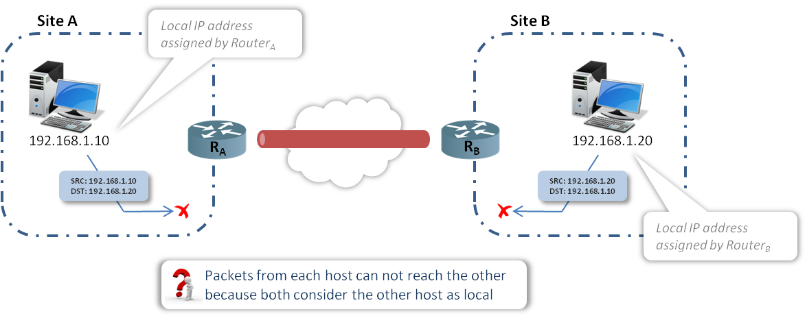
If HostA (192.168.1.10) uses the HostB IP address (192.168.1.20) to communicate with it or vice-versa, communication won’t be established because it considers that the destination host belongs to the same local network (192.168.1.0/24). Packets issued by HostA (or HostB) will not reach the other host on the remote site as HostA won’t get any ARP reply when trying to resolve the HostB IP address.
In order to solve this issue, it is obvious that we must convince each host that the other host is on a foreign network. That would cause them to send packets to the Router, which can then send them through the VPN tunnel.
In our described use case, this can be done by making the SiteA network appear as 10.0.1.0/24 when speaking to SiteB, and making the SiteB network appear as 20.0.1.0/24 when speaking to SiteA.
How this works in reality:
1 – When an IP packet is sent from HostA to HostB, the SRC address is set to the HostA IP address whereas the DST address is set to an IP address in the range of the new virtual network used on SiteA (SRC: 192.168.1.10 / DST: 20.0.1.20).
2- The packet is received by RouterA where a NAT policy rule is used to match any packet with SRC in the network range 192.168.1.0/24 and DST in the network range of 20.0.1.0/24 and to NAT the SRC address to 10.0.1.0/24.
3- The packets sent by HostA match the RouterA NAT policy rule and thus are SRC NATed (see schema), then routed in the VPN Tunnel to RouterB.
4- Packets from RouterA arriving at RouterB are reverse NATed and the DST IP address is set to HostB IP.
5- Packets sent from HostB to HostA will take the opposite path as described in the following schema.
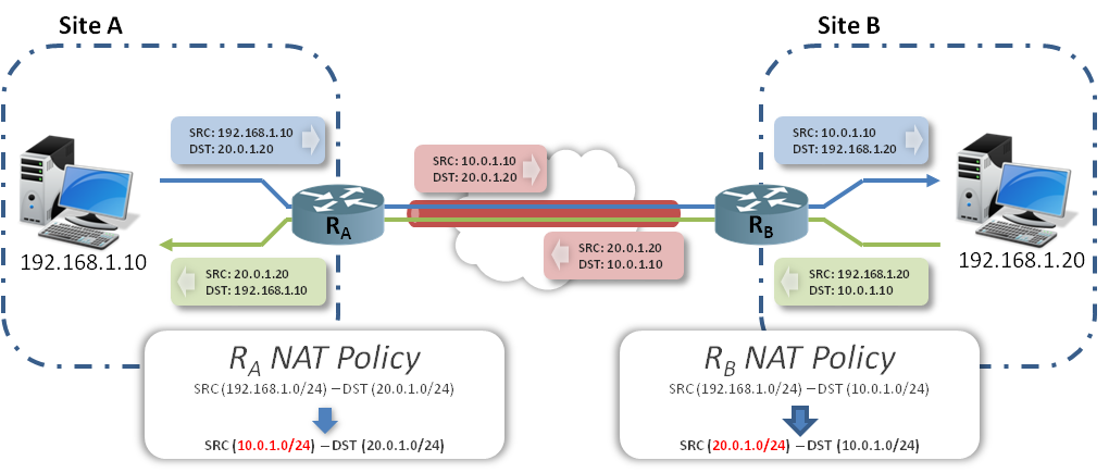
As described in the schema, traffic crossing the IPsec Tunnel uses the Virtual IP addresses defined in the NAT policy rules on both Routers.
Note: This setup is symmetrical and thus requires that both Routers support Policy NAT configuration. If for any reason this condition is not fit, the same result can be achieved by doing a Twice NAT policy on one side and not doing any address translation on the other side.
The following schema details how Twice NAT can be performed on one side to achieve the same results:
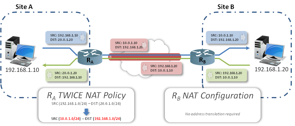
How this works in reality:
1 – When an IP packet is sent from HostA to HostB, the SRC address is set to the HostA IP address whereas the DST address is set to an IP address in the range of the new virtual network used on SiteA (SRC: 192.168.1.10 / DST: 20.0.1.20).
2- The packet is received by RouterA where a Twice NAT policy rule is used to match any packet with SRC in the network range 192.168.1.0/24 and DST in the network range of 20.0.1.0/24 and to NAT the SRC address to 10.0.1.0/24.
3- The packets sent by HostA match the RouterA NAT policy rule and thus are SRC and DST NATed (see schema), then routed in the VPN Tunnel to RouterB.
4- Packets from RouterA arriving at RouterB are then directly routed to HostB.
5- Packets sent from HostB to HostA will take the opposite path and are reverse NATed on the RouterA as described in the schema.
B: Dealing With VPN Isolation- “VRF aware IPsec VPN”
We need to connect two remote sites to a datacenter through an IPsec Security Gateway. Each remote site should only be granted the right to access to its dedicated Servers in the Data Center. The Security Gateway should guarantee that the traffic between each remote Site and its dedicated servers is fully isolated from the other traffic handled by the Security Gateway.
The following drawing illustrates the targeted setup:
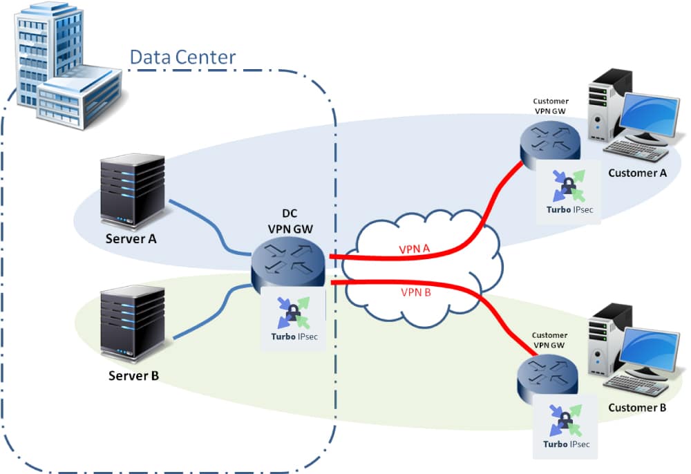
This setup can either represent a company network with a few servers hosted on a public cloud (data center) where isolation is required between servers to guarantee that data from one division is not accessible by the other divisions. Or it can also represent two companies co-hosting their server infrastructures in a data center with the same isolation constraints for data flows:
- CustomerA should only be entitled to connect to Server
- CustomerB should only be entitled to connect to ServerB.
- ServerA and ServerB should be completely isolated.
- Traffic from CustomerA and CustomerB to Security Gateway (DC VPN GW) should be secured.
Two main requirements have been raised in the section above:
- Securing traffic between customer site and Data Center.
- Isolating traffic inside the Data Center.
To fulfill the security requirement between the Customer’s site (Remote VPN Gateways) and Data Center (DC VPN Gateway), we will use IPsec Tunneling. The isolation requirement inside the DC VPN Gateway will be handled thanks to Virtual Routing and Forwarding (VRFs) and namespaces.
Two options can be foreseen to address the case. Each option uses a different segmentation approach to isolate the traffic on the server’s side. As both options are functionally equivalent, we will focus only on option B for the implementation part.
Option A
| Option B
Traffic segmentation based on vLans:
|
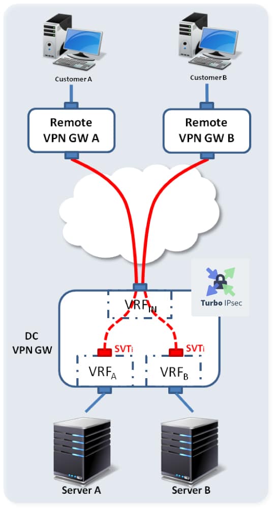 Traffic segmentation based on ports:
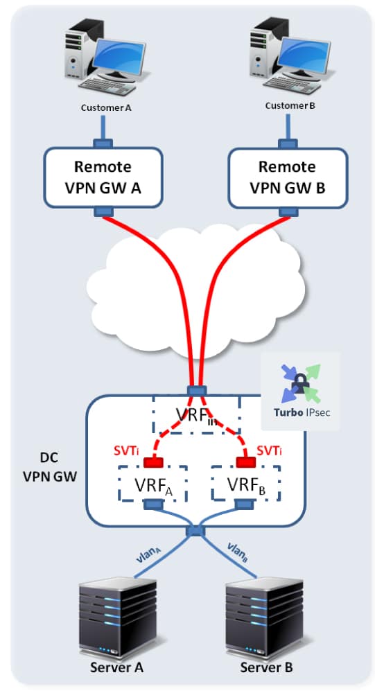
C: Implementation (Option B)
In order to cover the most complex use case, we will consider both customers using overlapping networks. We will also terminate the VPN on the loopback 1 interface on the DC VPN Gateway.
The following schema describes the chosen setup:
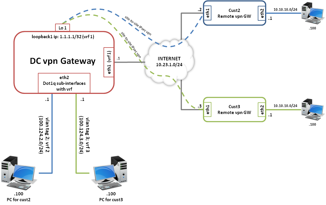
Our test criteria to validate that our setup is working as expected will be the following:
- PCs on either side should be able to successfully initiate/trigger an IPsec connection.
- PC 10.10.10.100 behind Cust2 Remote VPN Gateway should be able to initiate connection and communicate with 100.124.2.100 in VRF 2 behind DC VPN Gateway and vice versa.
- PC 10.10.10.100 behind Cust3 Remote VPN Gateway should be able to initiate connection and communicate with 100.124.3.100 in VRF 3 behind DC VPN Gateway and vice versa.
10.10.10.100 should be translated (port address translation) to the respective egress sub-interface IP on DC VPN Gateway when communicating with the 100.124.2.100 (incase of Cust2) and 100.124.3.100 (incase of Cust3).
D: Configurations
a. Linux based configurations
| PC for Cust2: ip link add name vlan2 link eth1 type vlan id 2 |
| PC for Cust3: ip link add name vlan3 link eth1 type vlan id 3 |
| Remote VPN GW Cust2: sysctl -q -w net.ipv4.conf.all.forwarding=1 # Configure VLAN # Configure SVTI # Configure IPsec ip xfrm state add src 10.23.1.2 dst 10.23.1.1 proto esp spi 2 mode tunnel enc ‘cbc(aes)’ ip xfrm policy add dir out tmpl src 10.23.1.2 dst 10.23.1.1 proto esp mode tunnel mark 0x1 # Add route |
| Remote VPN GW Cust3: sysctl -q -w net.ipv4.conf.all.forwarding=1 ip link set eth1 up # Configure VLAN # Configure SVTI # Configure IPsec ip xfrm state add src 10.23.1.3 dst 10.23.1.1 proto esp spi 2 mode tunnel enc ‘cbc(aes)’ ip xfrm policy add dir out tmpl src 10.23.1.3 dst 10.23.1.1 proto esp mode tunnel mark 0x1 # Add route |
| DC VPN GW: # Prepare netns ip netns add vrf2 ip netns add vrf3 ### To Servers ### To Customers ######### |
b. CLI based configuration
In the following section we will provide the same configuration files based on 6WIND’s CLI. For more details on the 6WIND CLI and its syntax, please visit this link: https://doc.6wind.com/turbo-ipsec/
We will be using the configuration file “myconfig” on all devices. After saving the configuration on each device and in order to apply it, the following command should be called:
| router{}apply conf myconfig |
| PC for Cust2: router{}edit conf myconfig router{conf:myconfig}rtg router{conf:myconfig}save |
| PC for Cust3: router{}edit conf myconfig router{conf:myconfig}eth1 router{conf:myconfig}rtg router{conf:myconfig}save |
| Remote VPN GW Cust2: router{}edit conf myconfig router{conf:myconfig}eth1 router{conf:myconfig}eth2 # Configure VLAN # Configure SVTI # Configure IPsec router{conf:myconfig-sec}sa esp 10.23.1.2 10.23.1.1 svti svti2 0x1000 tunnel aes-cbc router{conf:myconfig-sec}sa esp 10.23.1.1 10.23.1.2 svti svti2 0x1100 tunnel aes-cbc router{conf:myconfig-sec}exit # Add route router{conf:myconfig}save |
| Remote VPN GW Cust3: router{}edit conf myconfig router{conf:myconfig}eth1 router{conf:myconfig}eth2 # Configure VLAN # Configure SVTI # Configure IPsec router{conf:myconfig-sec}sa esp 10.23.1.3 10.23.1.1 svti svti3 0x1000 tunnel aes-cbc router{conf:myconfig-sec}sa esp 10.23.1.1 10.23.1.3 svti svti3 0x1100 tunnel aes-cbc router{conf:myconfig-sec}exit # Add route router{conf:myconfig}save |
| DC VPN GW: router{}edit conf myconfig # Prepare netns router{conf:myconfig}vrf2 router{conf:myconfig}vrf3 ### To Servers router{conf:myconfig}eth2 ### To Customers ############### # Create VLAN iface # Create SVTI iface # Configure IPsec router{conf:myconfig-sec}sa esp 10.23.1.1 10.23.1.2 vrf-id 2 svti svti2 0x1000 tunnel aes- router{conf:myconfig-sec}sa esp 10.23.1.2 10.23.1.1 vrf-id 2 svti svti2 0x1100 tunnel aes- router{conf:myconfig-sec}exit ############### # Create VLAN iface # Create SVTI iface # Configure IPsec router{conf:myconfig-sec}sa esp 10.23.1.1 10.23.1.3 vrf-id 3 svti svti3 0x1000 tunnel aes- router{conf:myconfig-sec}sa esp 10.23.1.3 10.23.1.1 vrf-id 3 svti svti3 0x1100 tunnel aes- router{conf:myconfig-sec}exit # Add route # Add NAT router{conf:myconfig}save |
Conclusion:
Securing data when crossing public networks or even when crossing shared private networks is a mandatory requirement to protect businesses. This blog addressed the most common problems that network builders have to face when dealing with securing and isolating traffic.
We described in this blog how, by moving physical interfaces into a separate VRF, we can create an elegant solution to configurations requiring isolation. At the same time, we used IPsec to securely obfuscate the original packets and payload and thus provide secure transport for the payload and hide content from prying eyes in untrusted parts of the transit network. Of course, we can consider also adding ACLs on physical interfaces to introduce a final layer of security to our setup; this could be a subject of a next blog.
It is obvious that there is more than one solution to tackle the described problem. This blog is not aiming at listing all of these solutions; we only need to give an idea on how the problem can be addressed and how we can apply the solution on a 6WIND Turbo IPSec vRouter. Contact us to discuss how 6WIND’s vRouter can help your network security.

Karim Mchirki is Pre-Sales Engineer at 6WIND.