Company infrastructure is distributed in different locations. Whether it is the increasing usage of cloud providers such as AWS or Azure, the multiplication of local decentralized offices, employees hitting the road and working from remote locations or the advent of the Internet of Things (IoT), more and more internal data flows are crossing untrusted communication networks. We can leverage IPsec VPNs to secure these communications using 6WIND vSecGW (Virtual Security Gateway).
In today’s blog post, we’ll see how to easily deploy 6WIND Virtual Security Gateway vRouter as a high-availability IPsec VPN Concentrator cluster sustaining 10k tunnels and 20 Gbps of secured IPsec traffic.
Overview: Use case with 6WIND Virtual Security Gateway vRouter
In this post, we’ll focus on the detailed configuration of 6WIND Virtual Security Gateway vRouter in the following use case:

In this setup, we emulate the connection of a farm of uCPEs to our VPN Concentrator cluster.
An IXIA traffic generator sends traffic in both directions. The packets are ciphered between uCPEs and the VPN Concentrator.
The configuration of 6WIND Virtual Security Gateway nodes involves the following features:
- VRRP interfaces
- IKE and IPsec synchronization over a dedicated link
- Active/Hot Standby high availability for seamless failover
- Advanced monitoring with metrics collected and sent to an EMS
- High performance ciphering and deciphering
- Enhanced scalability allowing 10k IPsec VPNs
Configuration
In previous blog posts we already saw how to deploy 6WIND vRouters in a wide variety of environments and we already provided guidelines on how to manage the configuration of the different instances.
In our case we deployed two 6WIND Virtual Security Gateway instances as VMs, each with 5 cores / 10 threads and 8GB RAM.
6WIND vRouter management is NETCONF/Yang based and you can find more information in this blog and associated webinar.
System And Network
Let’s first focus on the fast path configuration under “system”:
system
    fast-path
        port pci-b0s4
        port pci-b0s5
        core-mask
            fast-path 2-9
            ..
        advanced
            nb-rxd 4096
            nb-txd 4096
            ..
        ..
We dedicate 4 cores/8 threads to the data plane (cores 2 to 9), leaving 1 core/2 threads for the control plane.
LAN and WAN interfaces handled by the fast path are configured with static addresses inside the main vrf, and the dedicated synchronization link as well.
vrf main
    interface
        physical wan01
            port pci-b0s4
            enabled true
            description "Concentrator public interface"
            ipv4
                address 192.168.0.11/24
                ..
            ..
        physical lan01
            port pci-b0s5
            enabled true
            description "Concentrator internal interface"
            ipv4
                address 192.168.1.11/24
                ..
            ..
        physical sync01
            port pci-b0s6
            description "HA synchronization interface"
            ipv4
                address 192.168.100.1/30
                ..
            ..
On top of LAN and WAN interfaces, we configure 2 VRRP interfaces that are shared with the secondary node:
vrf main
    interface
        vrrp vrrp0
            description "Public VIP"
            version 3
            link-interface wan01
            garp-delay 1
            use-vmac true
            vmac-xmit-base true
            vrid 10
            priority 200
            preempt false
            advertisement-interval 100
            track-fast-path true
            unicast-peer 192.168.0.12
            virtual-address 250.0.0.2/24
            ..
        vrrp vrrp1
            description "Internal VIP"
            version 3
            link-interface lan01
            garp-delay 1
            use-vmac true
            vmac-xmit-base true
            vrid 11
            priority 200
            preempt false
            advertisement-interval 100
            track-fast-path true
            unicast-peer 192.168.1.12
            virtual-address 172.32.0.1/24
            ..
        ..
They are handling the virtual IP addresses that the outside world knows for this fully redundant VPN concentrator cluster.
We also configure static routes to send deciphered traffic back to the traffic generator and the ciphered traffic towards the uCPEs.
    routing
        static
            ipv4-route 0.0.0.0/0
                next-hop 192.168.0.1
                ..
            ipv4-route 172.26.0.0/24
                next-hop 172.32.0.250
                ..
            ipv4-route 172.27.0.0/24
                next-hop 172.32.0.250
                ..
            ipv4-route 172.28.0.0/24
                next-hop 172.32.0.250
                ..
            ipv4-route 172.29.0.0/24
                next-hop 172.32.0.250
                ..
            ..
        ..
IKE and IPsec configuration
We enable the IKE control plane in the main VRF. In addition to the ciphering parameters, a few tuning parameters ensure the scalability and the security of the VPN concentrator.
Ciphering
Instead of manually defining the configuration of each IPsec VPN, 6WIND Virtual Security Gateway allows the definition of templates that can be reused in different VPN definitions.
The configuration parameters of the 2 IKE phases are respectively handled by the ike-policy-template and ipsec-policy-template in our configuration:
        ike-policy-template vpnc_6wind_ike

            ike-proposal 1
                aead-alg aes128-gcm-96
                prf-alg hmac-sha1
                dh-group modp1024
                ..
            unique-sa replace
            rekey-time 0
            mobike true
            ..
        ipsec-policy-template vpnc_6wind_esp
            esp-proposal 1
                aead-alg aes128-gcm-128
                esn true
                ..
            start-action none
            close-action none
            replay-window 4096
            rekey-time 0
            ..
Both phases use the AES-GCM algorithm with a key size of 128 bits in our case.
We can now define the IPsec VPN characteristics by referencing these templates:
        vpn vpnc_6wind
            ike-policy
                template vpnc_6wind_ike
                ..
            ipsec-policy
                template vpnc_6wind_esp
                ..
            local-address 250.0.0.2
            local-id vpnc.6wind.com
            security-policy sp_vpnc1
                local-ts subnet 172.26.0.0/24
                remote-ts subnet 172.16.0.0/24
                ..
            security-policy sp_vpnc2
                local-ts subnet 172.27.0.0/24
                remote-ts subnet 172.17.0.0/24
                ..
            security-policy sp_vpnc3
                local-ts subnet 172.28.0.0/24
                remote-ts subnet 172.18.0.0/24
                ..
            security-policy sp_vpnc4
                local-ts subnet 172.29.0.0/24
                remote-ts subnet 172.19.0.0/24
                ..
            ..
The templates take care of all the cryptographic parameters. We only define the local IP address here, allowing connections to this address from any IP address. Note that the address defined here is the virtual IP address of the public VRRP interface built on top of the WAN interface. Additionally, we define the security policies with local and remote traffic selector subnets: initiators are allowed to negotiate the actual subnets protected by the Security Policies as subsets of these subnets.
High availability
IP address
We must ensure that the same node receives traffic on the LAN and the WAN interfaces and that this node is actually the one active from an IPsec point of view.
That’s why we define that the VRRP interfaces are grouped, thus binding their fate: each state transition of one interface implies the same transition for the other. This ensures that both virtual IP addresses are held by the same node at each time:
vrf main
    vrrp
        group group1
            instance vrrp0
            instance vrrp1
            notify-ha-group ha-group1
            ..
        ..
    ..
This VRRP group notifies the ha-group ha-group1 of each state transition. As we will see in the next paragraph, the IKE/IPsec HA daemon listens to these notifications via the listen-ha-group ha-group1 configuration item. As a result, the IKE daemon of each node is aware of the status of its respective sibling and knows if it should send or receive updates from the other node.
IKE and IPsec
To achieve the high-availability goal, we must keep the standby node synchronized with the active one regarding:
- The currently established IPsec VPNs (installed Security Associations and the negotiated secrets)
- Their current state (input and output sequence numbers of packets exchanged within a given IPsec VPN)
We enable this synchronization with the following configuration:
vrf main
    ike
        ha
            listen-ha-group ha-group1
            node-id 1
            interface sync01
            local-address 192.168.100.1
            remote-address 192.168.100.2
            seqnum-sync
                oseq-shift 65536
                sync-period-time 10s
                sync-period-packets 2
                ..
            ..
We first define the communication channel between both nodes with the local interface and remote- and local-addresses involved in the synchronization channel. Each node has its unique node-id. The configuration of vpnc2 is consequently the following:
            node-id 2
            interface sync01
            local-address 192.168.100.2
            remote-address 192.168.100.1
This synchronization process ensures that each VPN established on the active node is also propagated to the standby one.
Monitoring
6WIND Virtual Security Gateway collects and sends advanced KPIs to a remote Element Management System (EMS) running InfluxDB, a time series database, which can be displayed by an analytics frontend such as Grafana. More information is at https://github.com/6WIND/supervision-grafana.
The configuration is pretty straight-forward as we only need to enable the KPI retrieval at the system level and to configure the EMS target in the main VRF:
vrf main
    kpi
        telegraf
            influxdb-output url http://192.168.255.2:8086 database telegraf
            ..
        ..
    ..
system
    kpi
        enabled true
        ..
    ..
Operation and resiliency
Traffic startup
Let’s first establish a few IPsec VPNs by starting the traffic. We start the IXIA traffic generator and see that we can reach 18.9 Gbps of clear text traffic. With the overhead induced by the chosen IPsec algorithm this results in 20 Gbps of IPsec traffic between the uCPEs and the VPN concentrator:

We can monitor these IPsec VPNs from the VPN concentrator point of view:

Commands are available to list the established IPsec VPNs, get the total number of VPNs and retrieve the details of a particular one either from its originating IP address or from its originating ID.
We can also check that the traffic exchanged on the WAN interface is encrypted:

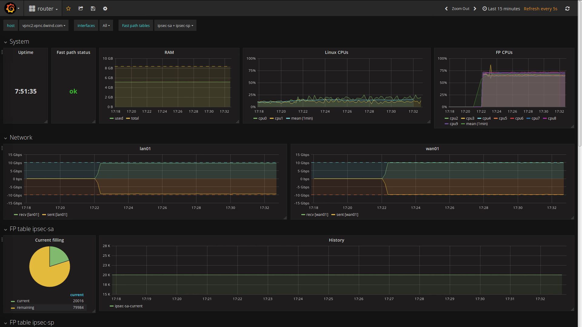
The monitoring dashboard available on the EMS provides an overview of the status:

Scaling to 10k VPNs
Let’s now establish 10k additional IPsec VPNs. We can follow the progress on the dashboard:

The 10k VPNs are successfully negotiated while dealing with 20 Gbps of IPsec traffic.
Seamless failover
Let’s take a closer look at the initial state of the cluster by comparing the configuration and the status of vpnc1 (left) and vpnc2 (right):
 and vpnc2 (right) 1")
The VRRP interfaces are declared with a higher priority on vpnc1, ensuring that this node becomes master initially. As a consequence, vpnc1 holds both WAN and LAN virtual IP addresses.
We then trigger the failover by simulating a temporary failure of the LAN network connection of vpnc1. Due to the grouping of the VRRP interfaces, vpnc2 takes over both virtual IP addresses:
 and vpnc2 (right) 2")
As both nodes synchronized the IPsec VPN states, vpnc2 could take over the traffic as soon as the failover occurred. From an external point of view, nothing has changed:
- LAN and WAN IP addresses have continuously been reachable
- The IPsec traffic has been ciphered and deciphered without interruption
The matching dashboard on vpnc1:

And the matching dashboard on vpnc2:
Conclusion
Using 6WIND Virtual Security Gateway vRouter to implement a VPN concentrator solution will bring multiple benefits:
- 6WIND vRouter can run in any environment including commercial-off-the-shelf (COTS) servers and common virtualization infrastructures
- 6WIND vRouter management is NETCONF/Yang-based for easy automation
- High IPsec throughput scaling with the number of cores allocated
- Scales to several thousands of IPsec VPNs with a high establishment rate
- Protection mechanisms against DDoS attacks
- VRRP and IKE/IPsec High Availability for seamless failover
- Advanced monitoring through KPIs exported to an analytics dashboard
Feel free to request an evaluation as well. We will be happy to hear from you.
This article was written by Aurélien DEGEORGES, L2 support engineer at 6WIND.